Table of contents
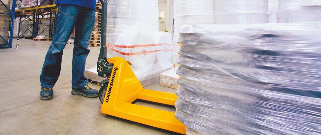
Every operator of an industrial truck must know the load capacity of their forklift or pallet jack and the payload. In the warehouse or during mobile operations, transporting activities must be carried out quickly, precisely, and safely. Since the goods being moved can vary in shape, size and weight, the situation must be re-evaluated at every step because as soon as loads are lifted and transported, different forces are generated.
Differentiation between nominal load capacity and actual load capacity
When operating forklifts or pallet trucks, a distinction must first be made between the rated load capacity and the actual load capacity (also: real or residual load capacity). Colloquially, the nominal load capacity is also referred to as the payload of an industrial truck. However, the term “load capacity”, which is also frequently used in this context, is incorrect.
The actual load capacity and the nominal load capacity are interdependent and must therefore always be considered together:
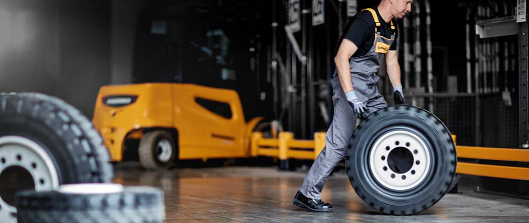
- The rated load capacity refers to the maximum carrying capacity of a forklift truck or lift truck or its load-bearing elements, such as fork units or angle elements, but also rims and tyres. It is measured in kilograms and is linked to the tare weight of the industrial truck. Dynamic forces are not taken into account.
- The actual load capacity determines the correct dimensioning of the industrial truck or the goods to be transported. The residual capacity is not applied to low lift trucks or tugs. For low-lift trucks, the concept of nominal load is used, and for tractors, the concept of tractive force and towed load.
The load centre of gravity – safe lifting and moving of loads
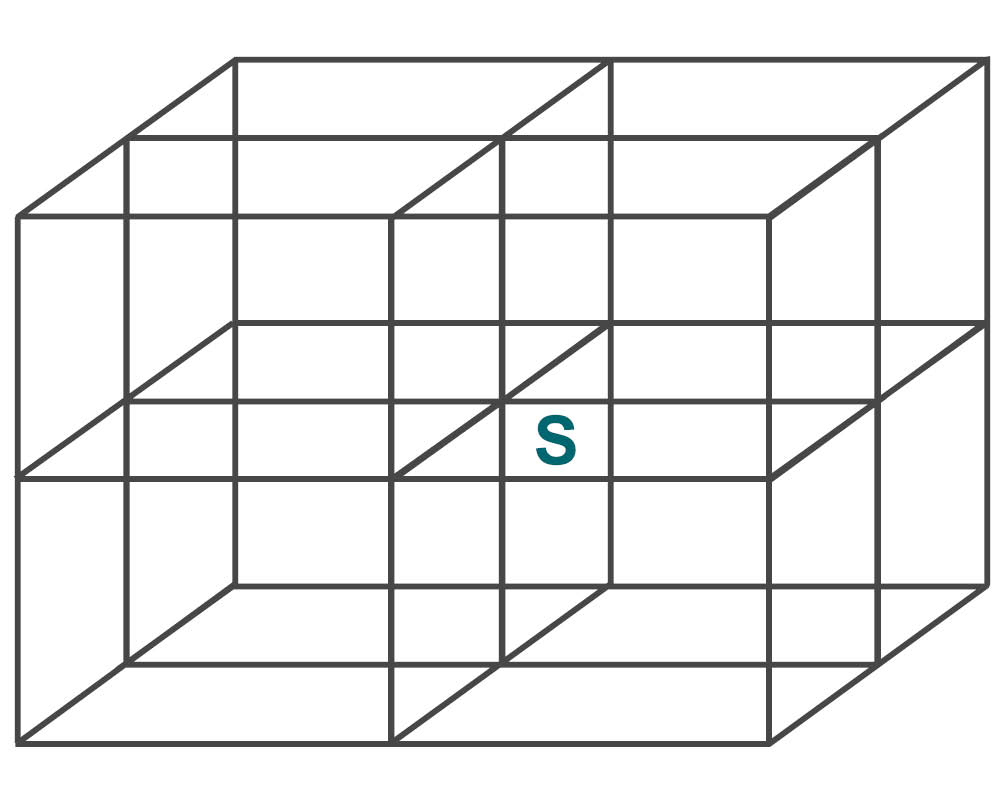
If a uniformly weighted load is to be moved with the forklift or pallet truck, the centre of gravity (S) is in the middle – provided that the load to be transported is cube-, cuboid- or cylinder-shaped.
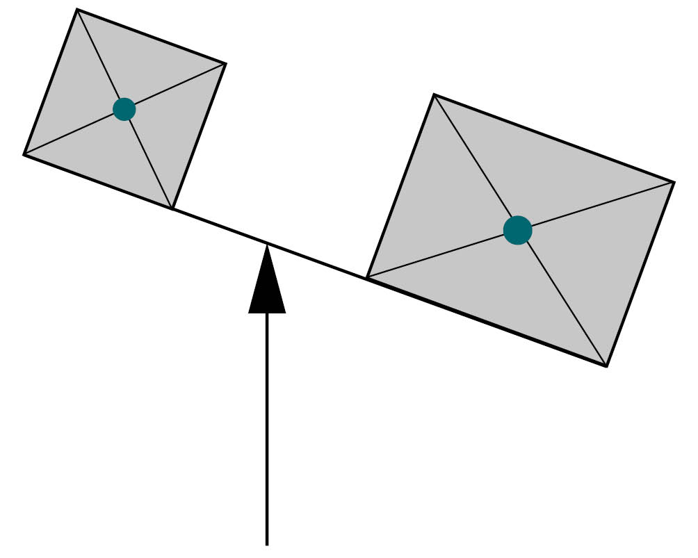
The mechanism between the load to be moved and the forklift or lift truck corresponds to the behaviour of a seesaw:
- Here, the load capacity depends on the load’s centre of gravity (S): The longer, higher and wider a load is, the more it influences the centre of gravity of a forklift or lift truck.
- The load capacity decreases with increasing lift height and load centre distance.
When a forklift or lift truck picks up a load, the material handling equipment can theoretically tip over at the pivot point (D) of its load axis. This is where the load moment acts. This is made up of the load (kg), together with the load centre distance (mm), and the dimension of the equipment constant from the centre of the load axis to the front edge of the fork back.
On the opposite side of the pivot point, the force of the greater deadweight (kg) of the forklift or pallet truck acts against it. In combination with the wheelbase, i.e., the length of the force arm (mm), everything forms the so-called counter-torque.
This physical behaviour can be reflected in the formulas according to the law of leverage:
- Load moment (M) = load (Q) x load arm (c + x).
- Counter moment (M) = force (F) x length of wheelbase (h)
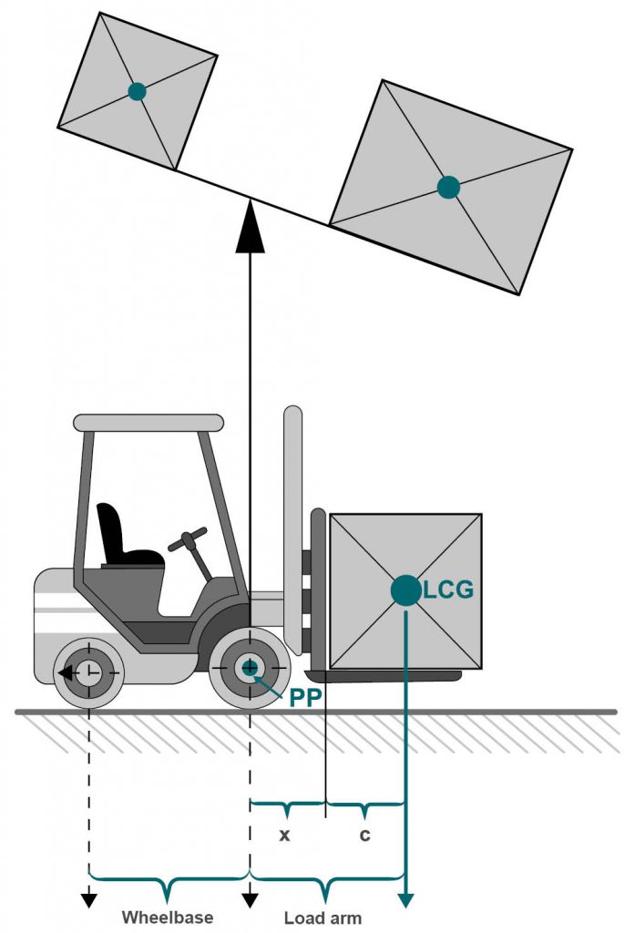
- Load centre distance (c) = horizontal distance of the load centre to the lifting device.
- Load distance (x) = dimension from the centre of the front axle to the lifting device (e.g., the back of the fork)
- Load centre of gravity (LP) = length of the load to be moved / 2
If the load centre distance increases, the forklift weight capacity is automatically reduced. Such situations can arise, for example, due to an unfavourable pallet position in the truck, even if the pallet load itself remains the same. In such a case, the truck may tip over even though the same loads were previously unloaded without any problems. The remaining load capacity of the forklift or pallet truck is no longer sufficient:
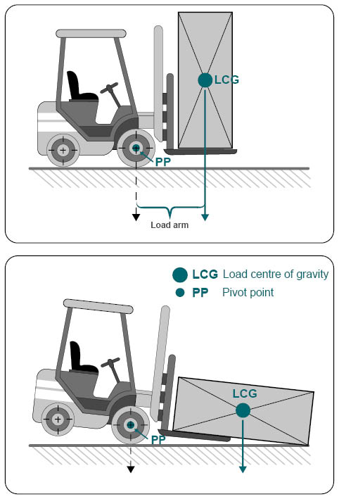
With uneven loads, the heavier side must always be picked up towards the back of the fork. In this way, the load centre distance is the smallest. Care should also be taken to ensure that the load is always directly against the back of the fork before it is transported.
The standardized load centre distance for forklifts with a rated capacity up to 10,000 kg is as follows:
- up to 1,000 kg load: 400 mm
- 1,001 to 5,000 kg load: 500 mm
- 5,001 to 10,000 kg load: 600 mm
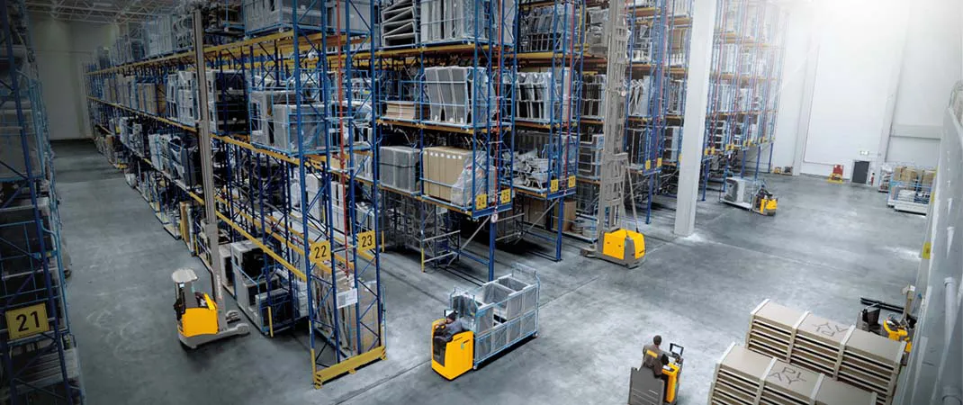
Centre of gravity for different industrial trucks
Forklifts and pallet trucks are divided into three different industrial truck groups.
| Group | Features | Vehicle Example |
|---|---|---|
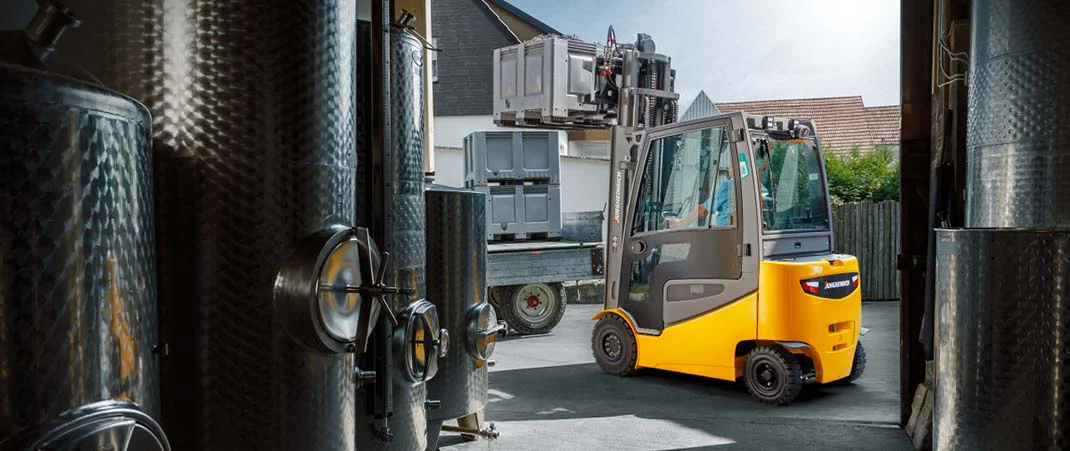
| Cantilevered industrial trucks | • Load centre is outside the wheelbase of the forklift truck • Counterweight or rear weight required for stability, e.g., battery for electric drive • have the highest rated load capacity due to the counterweight | Forklift |
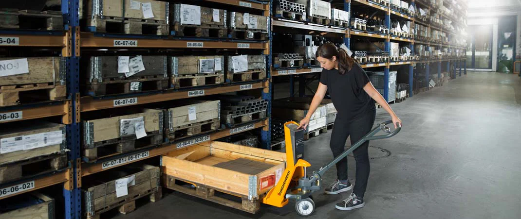
| Wheel-assisted industrial trucks | • Load centre lies within the wheelbase • No counterweight necessary for stability | Pallet Truck |
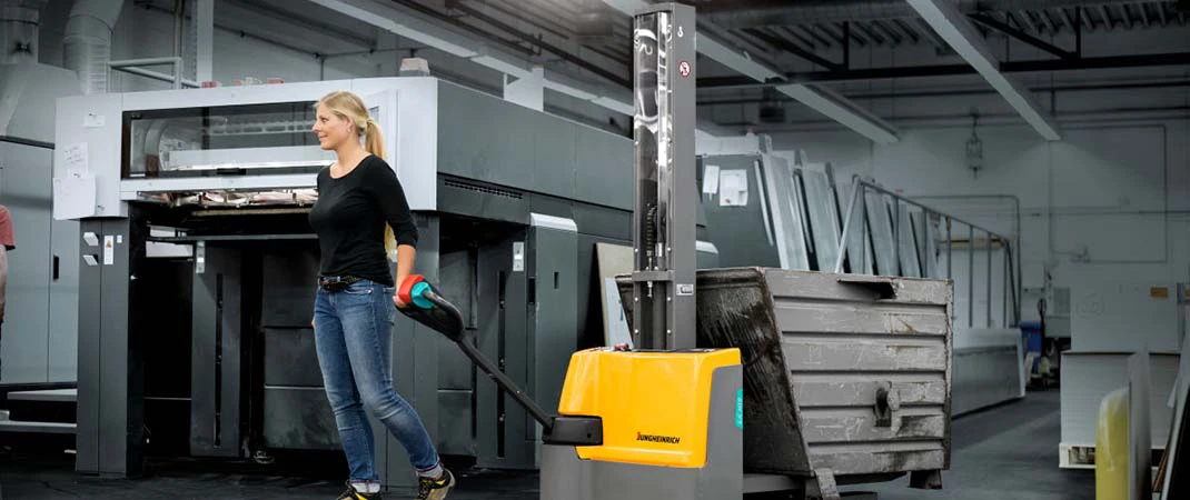
| Cantilever and wheel-assisted industrial trucks | • Load centre is located outside as well as inside the wheelbase • Load is picked up with the load arm extended • Load transport with retracted load arm • No counterweight necessary for stability | Reach Truck |
Calculating the residual load capacity in the load centre of gravity diagram
The lifting height has a decisive influence on the load capacity of forklift trucks and stacker trucks. For example, the standard lifting heights are specified in EC Directive 86/663 EEC, up to which a forklift truck or pallet truck must be able to lift the rated load without compromising stability:
- Lifting height = 2500 mm High lift truck as well as high lift pallet truck with maximum width over the forks or platform of 690 mm.
- Lifting height = 3300 mm Stacker in general
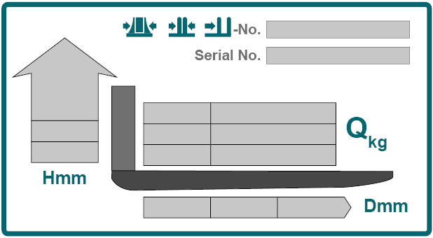
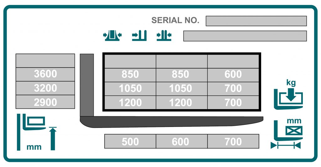
In every industrial truck with a mast in front of the front axle or on lifting attachments, there is a plate with a load capacity or load centre of gravity diagram. With the help of this diagram, you can calculate the load centre and the residual load capacity in order to correctly estimate the leverage effect during loading work. The diagram assumes a forklift or pallet truck with standard forks and a load centre in the middle of the truck. On the load capacity diagram, you can read the formula for the maximum rated load capacity:
- Load weight (kg) and standardized load centre distance from the back of the fork (mm) – taking into account the standard lifting height (mm).
If the load to be moved deviates from the nominal load capacity, this is referred to as the residual load capacity. By checking the load capacity diagram, it is possible to quickly determine whether the load to be moved can be safely moved to the desired height. The load capacity of a forklift truck depends on its weight: The heavier a vehicle, the more load-bearing it is. Exceptions can arise due to the following points:
- Different standardized lifting height
- Special shape of the lift mast
- Differently standardized load centre of gravity
- Detachable attachments
For practical purposes: Reading the payload diagram correctly
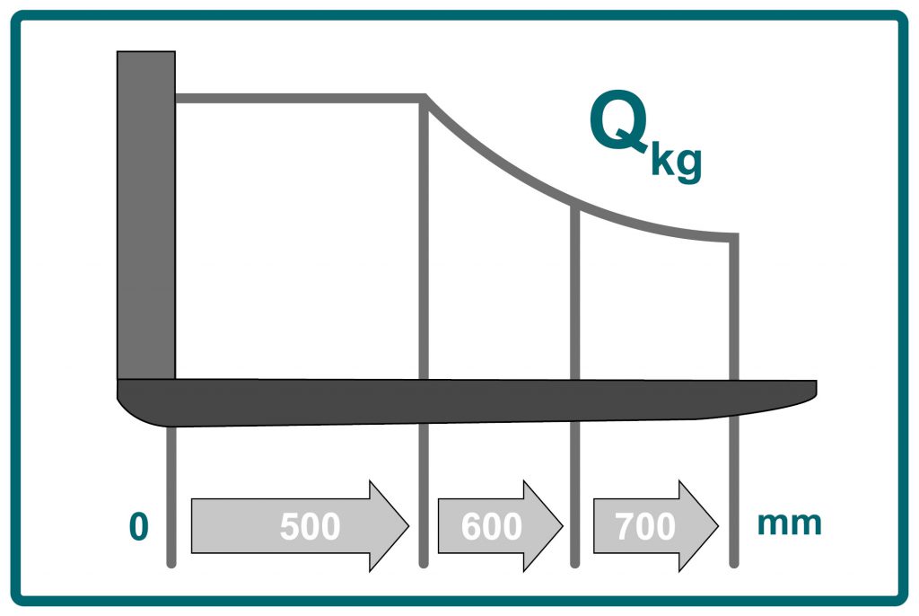
In order to prevent accidents at work, as well as damage to the transported goods or vehicle, it is of utmost importance that you read and interpret the payload diagram on the forklift or high-lift truck correctly. Usually, the diagram has three axes: on the right, you will find the possible carrying capacity indicated in ascending order in kilograms, and on the left, the information on the lifting height in millimetres. The lower axis shows the permitted load centre distances in ascending order from left to right.
The graphic shows a load capacity diagram for industrial trucks, the nominal load capacity of which changes as a function of the lifting height.
Because of this tripartition, it is possible to use two known quantities to determine the third. For example, you can find out to what height a transport item can be safely lifted if you know its weight and centre of gravity. But you can just as easily determine the maximum residual load capacity of a forkliftor industrial truck or the suitable centre of gravity based on a specific rack height.
When reading a payload chart, you must always keep in mind that the specifications apply only to use under normal storage conditions. Uneven floors, unevenly loaded pallets, or a movement of the lifted load have a significant impact on the load capacity and transport safety of an industrial truck, so the load capacity for these exceptional situations must be calculated separately.
Application example: Load capacity diagram for forklifts
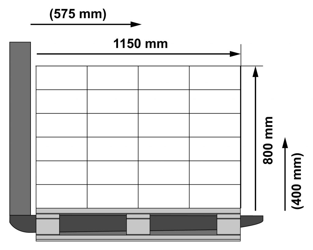
The following example will show you how to use the load diagram in practice. For this purpose, palletized cartons of the same size and weight are assumed as an example load:
- Height of the load: 800 mm
- Length of the load: 1150 mm
- Distances between load centre and load handling attachment: 400 mm vertical, 575 mm horizontally
Note:
- For loads with uniform weight distribution, the load centre is located in the geometric centre of the volume
- For rectangular loads with uniform weight distribution over the entire volume, the load centre is located in the middle at half the length, half the height, and half the width of the load
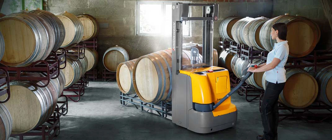
Adding attachments to forklifts and pallet jacks
If attachments must be used with the industrial truck during loading, the increased dead weight, as well as the load centre distance will change the nominal load capacity. For example, the residual load capacity is already reduced without load attachment if a fork extension is used. If additional accessories such as work platforms, tipping containers or crane booms are used, the real load capacity is reduced considerably. When choosing a load capacity forklift for your warehouse, consider both the maximum weight you’ll need to lift and the required height of operation. Likewise, understanding the pallet jack load capacity is essential for safe and efficient material handling in warehouses.
If a forklift or pallet jack is already equipped with detachable accessories by the manufacturer, these parts must have clear markings for the respective load capacity with regard to height and load centre distance.
FAQs about forklift and pallet jack load capacity
A pallet jack and forklifts’s load capacity primarily depends on the load’s centre of gravity (CG). The longer, higher, and wider a load is, the more it affects the centre of gravity of a forklift or pallet truck. Additionally, the load capacity decreases as the lift height increases, which changes the distance to the load’s centre of gravity.
Nominal load capacity, also known as rated capacity, refers to the maximum load (maximum static vertical load) of a forklift or pallet truck, including its load-bearing elements such as forks, angle attachments, rims, and tyres. This maximum load limit is measured in kilograms and is linked to the empty weight of the industrial truck. It doesn’t take dynamic forces into account. The rated load must be determined at standard lift heights and standardised load centre distances, and must be clearly displayed on the machine’s nameplate.
Residual load capacity is the remaining load capacity when there are limitations compared to the rated capacity. These limitations can occur due to factors like an increased load centre distance or a greater lift height. The residual load capacity must also be clearly displayed on a load capacity diagram on the forklift.
Image source:
© Jungheinrich AG, ©Getty Images – TommL